

You are here: Nature Science Photography – Visual acuity – Image sharpness II
How can we visualize the combination of various imaging components in terms of resolution? We should envision each component of the system functioning as a filter. Each component acts differently on the spatial frequencies that correspond to the different levels of detail in the subject. For example, one component might reduce the intensity to 80% at 50 Lp/mm, while another reduces it to 60%. The combined reduction would then be 50%*60% = 48%. Any detail in the 50 Lp/mm range would be reduced in intensity by this amount. We must therefore combine the resolution values of the components involved (capture lens, film/sensor, enlarging lens and photographic paper) in the analog as well as in the digital range to get a total resolution of the imaging system in order to be able to draw a conclusion about the performance of the imaging system.
Unfortunately, this is not as simple as it sounds. If the calculation is to be carried out in the original definition area „time“ or „space“, this must be done with the help of the cumbersome mathematical operation convolution. It goes somewhat more simply if we work in the definition range „frequency“. In this scenario, we first convert the signal using the Fast Fourier Transformation, and then multiply the resulting frequency component by the corresponding component’s frequency response (MTF). Finally, the inverse transformation can convert the frequency component back to the „time“ or „space“ definition domain. – Aren’t you happy that you wanted to know the exact details? However, there’s no need to panic, as we can simplify the entire process in just two steps.
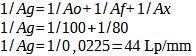
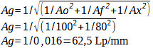
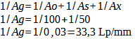
First, we can get an approximate idea of the resolving power of an imaging system with the help of two formulas. Assuming that the resolution corresponds to the spatial frequency at which the modulation is 30%, we can combine these values as follows (example calculations for a lens with 100 Lp/mm and a film with 80 Lp/mm, or a lens with 100 Lp/mm and the sensor of the Canon EOS-1Ds Mark II are provided).
Calculation 33 – Reciprocal formula lens and film
Calculation 34 – Square root formula lens and film
Calculation 35 – Reciprocal formula lens and digital camera
Calculation 36 – Square root formula lens and digital camera
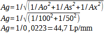
Ag: Total resolution of the system
Ao: Resolution of the lens
Af: resolution of the film
As: Resolution of the image sensor
Ax: Resolution of other components
Both formulas, along with their various still circulating derivatives, are only rough approximations, but they accurately reflect the important fact that the total resolution is lower than that of the individual components. With the reciprocal formula, you get a plausible impression of how far the resolution can drop. In fact, it can be higher. The square root variant rationalizes that, considering the circle of confusion, we should calculate the diameter of the combinations by taking the square root of the components. Beyond that, however, there is no really convincing theoretical justification for a single calculation method, and, strictly speaking, it makes no sense at all to summarize the resolution in a single number. That’s why you actually use MTFs. Therefore, it is optimal to utilize the formula whose outcomes align with your practical experience.
If you are still wondering why you should use 30% instead of maximum resolution, you did well to think through the math! Our visual system can separate the black and white lines of a bar test down to a contrast of 2%. However, in an image that has been run through various image generation and rendering stages, this slight difference is masked by the system’s inherent noise floor (grain, noise). Therefore, the maximum resolution value does not accurately describe the actual imaging quality. Useful, on the other hand, is a value at which true contrast is present (what would photography be without contrast?!), and for this reason the 30% value is usually used. Some authors also use the 50% value because it corresponds to the standard point (-3db) at which the bandwidth of an electrical signal is determined. Furthermore, it falls comfortably in the middle, allowing for consensus.
Next
Main Visual acuity
Previous The resolving power of digital output devices
 Since I started my first website in the year 2000, I’ve written and published ten books in the German language about photographing the amazing natural wonders of the American West, the details of our visual perception and its photography-related counterparts, and tried to shed some light on the immaterial concepts of quantum and chaos. Now all this material becomes freely accessible on this dedicated English website. I hope many of you find answers and inspiration there. My books are on