

You are here: Nature Science Photography – Visual acuity – Image sharpness I
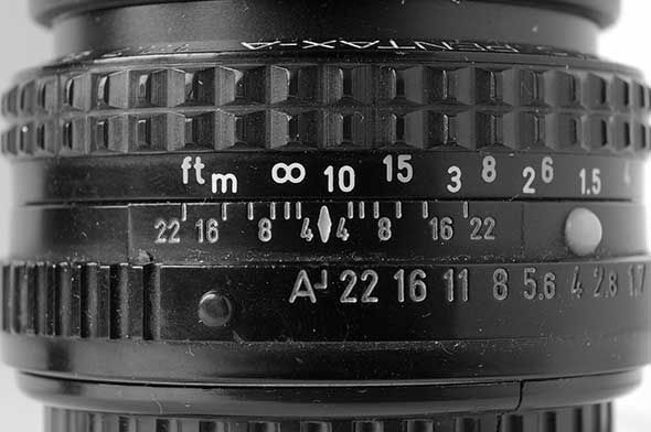
The depth-of-field scale used to be an indispensable standard on any lens, no matter how inexpensive. For some years now, it has unfortunately fallen victim to trends toward autofocus and cost-cutting. It simply consists of markings for a selection of available f-stops, placed to the right and left of the focus mark. These are often color-coded lines. We use them to determine the extent of the acceptably sharp area in each case, reading off from the directly adjacent distance scale. Conversely, it is possible to use the depth-of-field scale to determine the aperture required to bring the desired area into focus: Focus on the near or far point one after the other, note the distances, and turn the focus ring so that the two values come to rest approximately opposite two identical aperture marks. Then set the appropriate aperture, and you are on the safe side. The depth-of-field scale is thus a versatile tool, without which the photographer would lack these quick and important control options.
Technically, the depth of field scale shows how far we can deviate from the exact focus point without the circle of confusion exceeding the maximum allowable measure. This measure corresponds to the maximum allowable focus error x from the formula x = z*N. Consequently, the depth of field scale is nothing more than a simple scale that measures in units of the maximum allowable circle of confusion. For instance, moving the 1 m mark on the distance scale from the focus mark to the f/4 indicator on the depth of field scale extends the lens by 4 times the diameter of the underlying circle of confusion. 4*0.03 mm = 0.12 mm. If we continue to rotate to f/16, the extension will be 16 times the circle of confusion diameter: 16*0.03 = 0.48 mm.
To understand the „depth psychology“ of the two scales, let’s first go back to focusing for a moment. If the lens is set to infinity, the distance between its image-side main plane and the film plane exactly equals the focal length. If we focus on an object that is closer than infinity, the distance must be adjusted so that the sharp image is exactly in the film plane. Therefore, we must slightly extend the optics. For example, to focus from infinity to 5 m, it is on the order of 0.5 mm. It would be impractical to adjust these extremely small values by twisting the focus ring in a 1:1 ratio. The adjustment feel would be poor, and the resulting scale would be very small. For this reason, and because a mechanical conversion is needed anyway to turn the rotation into the differently directed pull-out movement, the focusing and lens pull-out are in a translation relationship to each other. For example, a rotation of 2 cm may be necessary to produce an extension change of 1 mm. The exact size of the transmission ratio need not interest us in detail. You only need to know that it exists and that twist and extension are proportional.
That was point 1. Point 2 refers to the depth-of-field scale, about which we stated above that it „measures in the unit of the maximum permissible circle of confusion“. If you now go and determine the distance between the individual aperture marks and the focus point as the zero point of the scale, you will find,
- that the aperture marks are symmetrically distributed to the right and left of the focus point
- that for example the mark for f/2 is twice as far away from the focus point as the mark for f/1 or f/16 is 16 times as far away as f/1
- that, for example, f/16 is twice as far away from the focus point as f/8, because f/16 is only half as large as f/8 and the depth of field doubles or halves from f-stop to f-stop
In no case, however, does the distance correspond directly to the diameter of the circle of confusion. This is due to the fact that the markings for the individual apertures are at distances from each other that are calculated from the circle of confusion diameter multiplied by the respective f-number multiplied by the transmission ratio of the lens thread and are therefore directly proportional to the maximum permissible circle of confusion diameter z. – This is necessary to ensure that the distance specifications and apertures yield the correct depth of field. The gradient factor of the lens thread also explains why the depth of field scales look different on different lenses: This measurement varies from manufacturer to manufacturer and from lens to lens. Nevertheless, the scale on all lenses shows the same thing in the same unit.
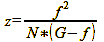
The appearance of the distance scale, on the other hand, depends strongly on the focal length, because the amount by which the lens extension OA of a lens with focal length f must be extended from the infinity position in order to focus on an object at distance G is given by formula 24:
Formula 24

The lens extension therefore scales with the square of the focal length. This explains why the length of telephoto lenses changes considerably when focusing: A 100 mm lens must be extended four times more than a 50 mm lens in order to focus from the infinity position on an object at a given shorter distance. The same scaling also works with regard to the depth of field: if you want to estimate how far the depth of field of the 100 mm lens extends using a 50 mm lens, you only need to multiply all distance values by four. Conversely, divide by four, assuming half the focal length.
We need to explain why the symmetrically arranged aperture symbols on the depth of field scale, when combined with the distance scale, often indicate a non-symmetrical depth of field. Let’s take a close look at the distance scale of any lens. I choose my Nikkor f/2.8 24 mm, with which I prefer to work. For instance, the distance between 0.35 m and 0.40 m is 6 mm, the distance between 0.40 m and 0.50 m is 8 mm, and the distance between 0.50 m and 0.70 m is also 8 mm. This distribution results from the distance scale being a linear mapping of the reciprocals of the distances. Figure 34 (Distance Scale) shows this, and it can be seen that the 50 m mark is twice as far from the infinity symbol as the 100 m mark because the reciprocal of 50 m (1/50 m = 0.02) is twice as large as the reciprocal of 100 m (1/100 = 0.01). Half of 50 m is 25 m (or 1/25 m = 0.04) and the mark is four times as far from the infinity symbol as 50 m and so on. This use of reciprocal values means that the aperture marks arranged symmetrically to the right and left of the focus point are offset by non-linearly distributed distance information.
I bet you would now like to know on what maximum permissible circle of confusion diameter the depth of field scales of your lenses are based. And you should, in order to assess how far you can trust them to meet your own imaging sharpness requirements. Unfortunately, most manufacturers do not specify this measure in the technical documentation of their optics and are not particularly forthcoming when asked. Nikon, for example, refuses to provide information on this, citing the confidentiality of such information. But you do not have to rely on these ladies and gentlemen and can determine z yourself as follows:
Variant 1:
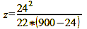
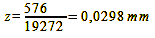
Set the focus of the lens with focal length f so that the infinity symbol is opposite the smallest aperture mark N on the depth-of-field scale, and note the distance indication G on the focusing ring opposite the focus mark. Next, input all the values in millimeters into formula 25:
Formula 25
For my Nikkor f/2.8 24 mm it results like this:
calculation 26

Variant 2:
Set any distance mark (e.g., 1 m) opposite the focus mark and determine the length of the lens from the bayonet to the filter thread with a caliper gauge, which preferably also displays 1/100 mm. Then turn the distance mark until it is exactly opposite one of the aperture marks (e.g., f/16) on the depth-of-field scale and determine the length of the now further extended lens again. It does not matter at which points of the lens you determine the values, as long as you choose the same one for both measurements. Now subtract the first value from the second and divide the result by the f-number. For the Nikkor f/2.8 24 mm used before, it looks like this: The first value is 46.51 mm, the second is 46.99 mm, and the difference is 0.48 mm/16 = 0.03 mm. Taking into account a small inaccuracy factor, this measurement is close enough to that of variant 1.
If you find the manufacturer’s circle of confusion too large and prefer a smaller one, you can leverage the direct proportionality between the distance between the aperture marks and z. In this case, you only need to divide the aperture numbers by two. So with f/16 set, for example, you use the marks for f/8.
The second way to control the depth of field on SLR cameras is with the depth of field preview button . If you press it, the aperture closes from the open „setting aperture“ to the „set working aperture“, and you can visually check the area of focus on the now darker viewfinder image. However, this increasing darkness with stopping down (small aperture = low light) can greatly reduce the detectability of the effect at low subject brightness. Modern SLR cameras typically lack a depth of field preview button due to the motor driving the aperture and mirror release. This would necessitate a separately controlled aperture mechanism, thereby increasing the complexity and cost of the camera body. Nevertheless, since it is an important tool for judging depth of field, its presence or absence should influence a serious photographer’s purchase decision.
Next Circle of confusion and diffraction slice – Not every aperture is a good aperture
Main Visual acuity
Previous Depth of field and image format
If you found this post useful and want to support the continuation of my writing without intrusive advertising, please consider supporting. Your assistance goes towards helping make the content on this website even better. If you’d like to make a one-time ‘tip’ and buy me a coffee, I have a Ko-Fi page. Your support means a lot. Thank you!
 Since I started my first website in the year 2000, I’ve written and published ten books in the German language about photographing the amazing natural wonders of the American West, the details of our visual perception and its photography-related counterparts, and tried to shed some light on the immaterial concepts of quantum and chaos. Now all this material becomes freely accessible on this dedicated English website. I hope many of you find answers and inspiration there. My books are on