You are here: Nature Science Photography – Lightness and color – Lightness and color in photography
Just like the silver halide crystals in analog film, the photocells and the sensors they make up in digital imaging technology are basically color-blind. In order to produce a colored image, we also have to split the incident spectrum into its components. This division is done in different ways depending on the manufacturer.
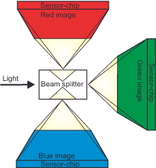
In the one-shot in multiple-chip technique (or 3-CCD method), the light is divided by prisms and mirrors into three beam paths, which simultaneously expose separate sensor surfaces for the red, green and blue areas of the spectrum. The advantage of this technique is that, in contrast to the 1-chip technique presented below, no interpolation algorithms have to be applied, and therefore no loss of sharpness or moire effects occur. However, the 3-CCD method also has a major disadvantage because the price is incomparably higher than for a comparable 1-CCD camera due to the two additional CCDs and the complicated optics.

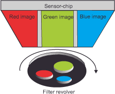
The three-shot technology works with only one sensor, in front of which the three filters rotate on a turret. However, since the resulting three images are not captured in a single instant, such cameras are only suitable for still subjects.

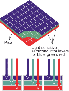
The technology developed by the company Foveon takes an intermediate route. It takes advantage of the fact, also used in analog silver film, that light penetrates a substrate to different depths depending on its wavelength range. As a result, the layers sensitive to blue, green and red are arranged one below the other, as is the case with analog silver film. The great advantage of this method is that a value for each wavelength range is determined at every pixel, which provides a very accurate picture of the intensity distribution.

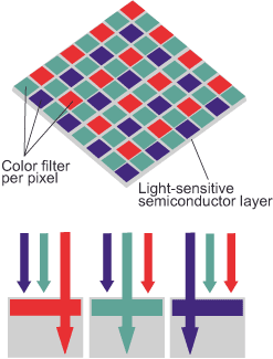
The three techniques described above are contrasted by the one-shot technique, in which the pixels lying next to each other in the chip’s raster are vaporized alternately with a blue, green and red filter layer. In this way, only a relatively simply constructed sensor is needed to capture all the color information at the same moment, and this makes for relatively small and cheap cameras. The most common distribution here is the Bayer filter pattern, in which one row of green-sensitive pixels alternates with another blue- or red-sensitive one, and which has twice as many green-sensitive pixels as blue- or red-sensitive ones. In this way, the high sensitivity of our visual apparatus to the medium-wave green-yellow range of the spectrum is to be imitated, from which the digital technique also obtains the brightness information that is particularly important for the impression of sharpness. The other digital imaging techniques also pay increased attention to the green value with a second exposure in this part, and the manufacturers of analog color-negative and reversal products now frequently equip them with a fourth, cyan-sensitive layer for the same reason.

Bayer pattern sensors have twice as many green pixels as red and blue pixels because our visual system is most sensitive to the mid-wave region of the spectrum.
Through each of the described filter types, we obtain three grayscale images representing the brightness distribution for the long-wave red, the medium-wave green, and the short-wave blue regions of the spectrum. It is simple to convert these grayscale images into color values that align with the additive RGB color model. Let’s imagine we take a picture in which only red, green and blue are present. What happens? The red color would produce a signal only in the photodiode located under the red filter, green under the green filter and blue under the blue filter. The other values would be zero. Red 100 % Green 0 % Blue 0 % then corresponds to red in the RGB model. Red 0 % Green 100 % Blue 0 % corresponds to green. Red 0 % Green 0 % Blue 100 % corresponds to blue. However, since we do not work with percentages in the digital domain, the analog/digital converter converts the analog voltage values of the photodiodes into binary values whose number of gradations corresponds to its bit width. If we were to assign one bit each to red, green and blue, we would get a color scheme of eight colors containing the primary colors with either 0% or 100% saturation. The VGA palette represents these eight colors in a similarly small color scheme of 16 colors. It is the minimum standard for color monitors. However, to display more complex color gradients and photorealistic images, we need a larger number of writable saturation levels per color, i.e., more than one bit per basic color. The standard is therefore the 24-bit color scheme (True Color), in which each color has 24 : 3 = 8 bits available. Each bit can take two values, zero and one, and thus there are 8 x 2 = 16 values that can occur in any combination. So 16² = 256 gradations per color are possible, each expressing its own degree of saturation. Altogether we come with it on 256 * 256 * 256 = 16,777,216 possible colors.
We humans can distinguish 200 color gradations within the spectrum and 500 brightness gradations, as well as 20 saturation gradations within each color level. That makes 200 * 500 * 20 = 2,000,000 different colors. Against this background, the 16.7 million colors of the True Color display should be fully sufficient to enable a true-to-life color representation.
In this binary notation, red 100 % green 0 % blue 0 % becomes red 256 green 0 blue 0. For black, all three values would equal 0; however, for white, the values would equal 255. All values in between, where red, green and blue each have the same proportion, are gray levels, of which there are 256. Of course, all mixed colors are formed according to the same scheme. A dark blue, whose analogous values would be Red 5% Green 45% Blue 96%, would be binarily designated as Red 14 Green 114 Blue 245.
In the case of techniques that use three individual sensors or a three-layer sensor for the different wavelength regions of the spectrum, the values for red, green and blue are determined directly at each pixel. This is not possible with Bayer pattern sensors. They generate color through the demosaicing process. The process of translating the primary color filter array (CFA) into a finished image with full color information in each pixel is known as demosaicing. Since each sensor location provides information about only one region of the spectrum (shortwave/blue, mediumwave/green, longwave/red), the demosaicing algorithm must interpolate the two missing data in each case, „guessing“ as it were. In doing so, it relies on the neighboring pixel values and makes what is called an „educated guess“. The individual pixels are grouped into arrays measuring 2×2 elements and are calculated against each other in terms of their spatial and/or chromatic relationships. The interpolation works because the raster provides enough information about the surroundings of a pixel to make a qualified guess about the real color value at that location. The mathematics behind this varies from manufacturer to manufacturer and is a closely guarded secret because it plays a decisive role in determining image quality. Furthermore, manufacturers consistently publish new algorithms. The currently highest-quality algorithms also incorporate stored knowledge about a large number of natural scenes into their calculations, making them adaptive to the image content.
Next Where and What – Brightness and color in image design
Main Lightness and Color
Previous Analog image carriers – reversal film
If you found this post useful and want to support the continuation of my writing without intrusive advertising, please consider supporting. Your assistance goes towards helping make the content on this website even better. If you’d like to make a one-time ‘tip’ and buy me a coffee, I have a Ko-Fi page. Your support means a lot. Thank you!


 Since I started my first website in the year 2000, I’ve written and published ten books in the German language about photographing the amazing natural wonders of the American West, the details of our visual perception and its photography-related counterparts, and tried to shed some light on the immaterial concepts of quantum and chaos. Now all this material becomes freely accessible on this dedicated English website. I hope many of you find answers and inspiration there. My books are on