

You are here: Nature Science Photography – Visual acuity – Image sharpness I
No matter the manufacturer or format, a lens is only really sharp in a certain aperture range – the sweet spot. The frames of this window are aberration on the large aperture side and diffraction on the small aperture side.
Aberrations are errors caused by deviation from the ideal optical image, resulting in a blurred and/or distorted image. One of the aberrations is chromatic aberration. It is caused by the fact that the refractive index of each material varies with the wavelength of the incident light (this is called dispersion). However, as the refractive indices of the glasses in an optical system vary, so does the focal length of the imaging system and thus the scale of the partial images produced by light at different wavelengths. These are of different sizes, and this leads to color fringes, edges and blurring in the image. We refer to this first effect as lateral chromatic aberration. In addition, however, the section width and thus the distance of the image from the last optical surface of the system also depend on the refractive index (and thus indirectly on the wavelength). For this reason, the partial images of the different wavelengths are imaged at different points, and it is not possible to focus on all of them at the same time. We refer to this second effect as longitudinal color error, which also results in image blurring. The main remedy against chromatic aberration is the use of two lens segments, so-called achromats, made of glass types that have the same refractive index for two wavelengths. The apochromats, identified by the abbreviation APO on the optics, represent a further development of this approach. They utilize glass types with abnormal dispersion, thereby maintaining the same refractive index across three wavelength ranges. Because of the special glass types required, apochromatically corrected optics are very expensive.
Spherical aberration (also called aperture aberration) causes light rays incident parallel to the axis or emanating from the same object point on the optical axis to not meet at the same point after passing through the optical system. Lenses that suffer from spherical aberration provide a soft and somewhat blurry, but sharp image. Fine object details are still visible, but their contrast is reduced. Spherical aberration can therefore be used to good effect to achieve a soft focus effect. For this purpose, there are lenses that allow spherical aberration to be adjusted continuously over a wide range. Spherical aberration is corrected by using lenses that have an aspherical surface. Since it is costly to grind such aspherically curved surfaces, such corrected lenses are particularly expensive.
Coma (from the Latin coma meaning hair or tail) is an imaging error caused by the fact that light rays coming from object points off the optical axis are also bundled off this axis. In uncorrected optical systems, this occurs asymmetrically, so instead of a sharp diffraction disc, an image point with a „tail“ directed toward the edge of the optics is produced, which gives the phenomenon its name. Stopping down can mitigate this. Aplanates are lenses in which the coma is completely corrected.
Astigmatism (also pointlessness) occurs because rays of the meridional plane incident obliquely to the axis intersect at a different point than the rays of the sagittal plane. This leads to the formation of two distinct image shells, each with varying degrees of curvature. The points appear as radial strokes on one image shell and as tangential strokes on the other. Lenses in which astigmatism is corrected are called anastigmats.
Aplanat and anastigmat are now merely historical designations, as these corrections have become standard in current optics.
When a lens exhibits an image field curvature, it generates the image on a curved surface rather than a plane. The position of the ray intersection point along the optical axis then depends on the image height, i.e., the further away the object and thus the image point are from the axis, the more the image point is shifted in the axial direction. For this reason, the flat film or image sensor cannot produce a sharp image everywhere. If you focus on the center of the image, the edge is out of focus, and vice versa. The clever calculation of the lens arrangement can keep the image field curvature below a certain threshold. Some special cameras compensate for image curvature by pressing the image carrier against an appropriately curved surface.
A final aberration is distortion. It causes straight lines whose images do not pass through the center of the image to be reproduced curved. The distance of an image point from the center of the image depends in a non-linear way on the height of the corresponding object point. In other words, the image scale depends on the height of the object point. Barrell distortion occurs when the magnification decreases as the height increases. Then a square is imaged with outward curved sides and looks a bit like a barrel. We refer to the opposite case as pincushion distortion. Wavelike distortion can also occur when the first two types of distortion overlap to different degrees. This results in the curvature of straight lines into wavy lines on both sides.
The factors combined to form aberration are largely under the control of the engineers and can be virtually eliminated even at large apertures by appropriately elaborate design. – The designers at Zeiss or Leica prove this time and again. However, these aberrations cannot be calculated „just like that“. So if you want to know how well a particular lens performs in this respect, you need to consult test reports or take comparison shots at different aperture settings. The generally accepted rule is that aberration is at its lowest when stopped down two to four stops below the maximum aperture. From this aperture stop, the window to sharp images opens. How large it is, i.e., how far it extends into the range of small apertures, depends on the size of the circle of confusion on which it is based. The smaller the aperture, the stronger the diffraction that inevitably accompanies it. – The short way to maximum image sharpness is therefore not „stop down until the doctor comes“.
We have already learned something basic about diffraction in the section „Diffraction as a physical limitation“ in the chapter “ The resolving power of the visual system“. To save you the trouble of scrolling back, I will recapitulate briefly. Light waves normally travel in straight lines through space. When light waves encounter or traverse an obstacle in close proximity (defined as within a few wavelengths), they experience a deflection from this straight path on the opposite side. We call this process diffraction, and it is an unavoidable physical effect independent of the quality of the optics. The smaller the aperture, the greater the impairment of the image due to diffraction. This dispersion in different directions causes the light waves to no longer travel the same distance, but instead, they partially depart from their original direction of oscillation. This causes them to overlap and complement each other at one point or to completely or partially cancel each other out at another. This superposition (interference) produces a diffraction pattern (also called diffraction disk) that has the highest intensity where the waves add and the lowest where they cancel. If we would measure the intensity at each position of a straight line, we would get a band similar to the one shown in figure 4 b („Diffraction at different large apertures“ in chapter „Diffraction as a physical limitation“). A perfectly round and therefore ideal aperture would produce a diffraction pattern called the Airy disk after its discoverer, the British astronomer Sir George Airy (1835-1892). Transferred to a more practical case, we can imagine the diffraction as a water hose. If there is enough pressure, the water exits the hose as a nearly circular jet. However, if we slightly compress the free opening with our fingers, the jet separates into a relatively wide fan.
Here we come back to our already mentioned important reference: If the diffraction disk exceeds our maximum permissible circle of confusion, it impairs the sharpness of the image. Then the point present on the subject side is no longer imaged as such due to the deflection of the light waves but is expanded to a disk. So the question is: How far can we stop down without running the risk of counteracting the greater depth of field achieved by too large diffraction discs? To find the answer, let’s go a little further into physics.
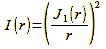
The light intensity I(r) behind an aperture follows the first-order Bessel function J1(r), where r stands for the radius of the aperture:
Formula 26
With this, we can calculate the airy disk with its outward fading rings, which only mean that the light intensity decreases to zero at regular intervals. Figure 38 is the graphical representation of this
oscillation around zero. In fact, an infinite number of these oscillations exist, with the first zero point containing about 84% of the intensity. This lies at:
Calculation 27

λ = Wavelength of light
R = Radius of the opening/aperture
The size of the diffraction disk is inversely proportional to the aperture. That is, the larger the aperture, the smaller the diffraction disk. In addition, its size is proportional to the wavelength of the light. The shorter the wavelength of the light, the smaller the diffraction disk.
The distance between the aperture and the film can be summed up as the focal length f. Since the aperture’s diameter D is given by the function f/D, we can directly figure out that the diffraction disk’s diameter at the first zero point is given by the following function:
Formula 27

λ = Wavelength of light
N = Aperture number
Applying this to an actual situation can be challenging, as light typically consists of a continuous spectrum spanning from 380 to 750 nm. We should actually take this integration into account. But we do not. For approximation, we use the wavelength to which our visual system is most sensitive. This is the green-yellow part at 555 nm (0.000555 mm). Based on this, we get:
Calculation 28
As already mentioned, the circle of confusion relevant for the film plane depends on the magnification scale and thus indirectly on the image format. For the 35 mm format, with an 8x magnification, the circle of confusion is typically 0.032 mm, calculated as 0.032/0.00135383 = 23.64. At aperture 22, the diameter of the diffraction disk at the first zero point is thus, in this case, as large as our maximum permissible circle of confusion. If, on the other hand, we calculate with the stricter value of 0.0091 mm, which follows from the average 20/20 vision, we get 0.0091/0.00135383 = 6.72. Thus, the diffraction limit is already between f/5.6 and f/8. – A considerable difference with respect to the maximum achievable depth of field. Using an average value of 0.025 mm, we can calculate 0.025/0.00135383 = 18.5. Thus, we can easily stop down to f/16.
Table 9 compiles the parameters determined according to this scheme for the common image formats. Due to the partly different aspect ratios, crop enlargements may be necessary to arrive at the final format. Accordingly, the data can then shift. The diffraction-limited aperture values are rounded in each case. The progressive value refers to 0.025 mm.
| Image format | Normal focal length | Magnification to 20×25 cm | Circle of confusion conservative / progressive | f/… diffraction-limited |
| 1/2.5“ 5,7×4,3 mm | 7 mm | 44x | 0,0058 mm / 0,0045 mm | f/4.0 / f/2.8 |
| 1/1.8“ 6,8×5,1 mm | 9 mm | 35x | 0,0073 mm / 0,0057 mm | f/5.6 / f/4.0 |
| APS-C 22,5×15 mm | 30 mm | 11x | 0,023 mm / 0,018 mm | f/16 / f/11 |
| 35 mm | 50 mm | 8x | 0,032 mm / 0,025 mm | f/22 / f/16 |
| 6×6 cm | 80 mm | 5x | 0,051 mm / 0,04 mm | f/45 / f/32 |
| 6×7 cm | 100 mm | 4x | 0,064 mm / 0,05 mm | f/45 / f/32 |
| 4×5“ | 200 mm | 2x | 0,128 mm / 0,1 mm | f/90 / f/64 |
| 8×10“ | 400 mm | 1x | 0,25 mm / 0,2mm | f/180 / f/128 |
From the table, we can read something important: Starting with 35 mm, the sweet spot changes with the image format. As the sweet spot expands, the window of practically usable apertures also expands, reducing the need to enlarge 4×5″ or 8×10″ to reach a final format of 20×25 cm, for instance. For this reason, the circle of confusion or diffraction discs in the negative may be larger. Conversely, to maintain the same final format, we must enlarge the smaller formats much more, and correspondingly reduce the circle of confusion or diffraction discs in the negative to avoid diminishing the print’s impression of sharpness. If the APS-C format’s sweet spot is just large enough to function effectively, aberration and diffraction limitations clash with 1/1.8″ and 1/2.5″ sensors, as well as the similarly large 8×11 mm Minox format, causing them to occupy the same aperture and leaving almost no window. Due to the increased diffraction, the optics of these formats do not allow to stop down further than f/5.6 or f/8 for good reason. In order to provide at least a „good“ aperture, they have to eliminate the aberration in the wide aperture range by very good correction.
Due to their short standard focal lengths compared to the 35 mm format, the small digital sensors compensate for their less pronounced ability to stop down by providing a relatively large, acceptably sharp area without requiring any significant stop down. Table 10 presents a comparison of these values across the individual formats. In this respect, their problem is rather that they cannot be opened far enough at all to clear a subject from the background through shallow depth of field. 35 mm and medium format have clear advantages in this last respect but are often a bit tight with regard to maximum depth of field due to the relatively early onset of diffraction limitation. – With the apertures f/11 (35 mm) and f/22 (medium format), which are considered maximum values from a practical point of view, one does not get very far. The absolute depth of field values are close to each other (assuming a format-equivalent aperture). With the large formats 4×5″ and 8×10″, on the other hand, we see a decrease in depth of field at the format-equivalent apertures. However, this doesn’t matter because, first, their sweet spot is large enough to compensate for this by stopping down further, and second, cameras in these formats have adjustment capabilities that allow for the superposition of the object and image planes. This focus stretching, according to Schimpflug (named after the Austrian officer and cartographer Theodor Scheimpflug, 1865 – 1911, who developed it in 1907) allows both foreground and background to be shown in sharp focus without any problems. With it, large-format cameras have an unassailable advantage because you can always stay within the range of the optimum aperture and control the depth of field by tilting the lens and/or film standard. – The wonderfully sharp images of numerous calendars and art prints bear eloquent witness to this! There are a few lenses and accessories available for 35mm and medium format cameras that mimic this adjustability.
| Format | Normal focal length | f/stop | Circle of confusion conservative / progressive | Distance | Near point | Far point | Depth of field |
| 1/ 2.5“ | 7 mm | 2,8 | 0,0058 mm | 5 m | 1,88 m | ∞ | ∞ |
| 1/ 2.5“ | 7 mm | 2,8 | 0,0045 mm | 5 m | 2,19 m | ∞ | ∞ |
| 1/ 2.5“ | 7 mm | 4 | 0,0058 mm | 5 m | 1,49 m | ∞ | ∞ |
| 1/ 2.5“ | 7 mm | 4 | 0,0045 mm | 5 m | 1,76 m | ∞ | ∞ |
| 1/ 1.8“ | 9 mm | 2,8 | 0,0073 mm | 5 m | 2,21 m | ∞ | ∞ |
| 1/ 1.8“ | 9 mm | 2,8 | 0,0057 mm | 5 m | 2,52 m | 301,42 m | 298,9 m |
| 1/ 1.8“ | 9 mm | 4 | 0,0073 mm | 5 m | 1,79 m | ∞ | ∞ |
| 1/ 1.8“ | 9 mm | 4 | 0,0057 mm | 5 m | 2,08 m | ∞ | ∞ |
| APS-C | 30 mm | 5,6 | 0,023 mm | 5 m | 2,92 m | 17,32 m | 14,39 m |
| APS-C | 30 mm | 5,6 | 0,018 mm | 5 m | 3,21 m | 11,28 m | 8,07 m |
| 35 mm | 50 mm | 8 | 0,032 mm | 5 m | 3,39 m | 9,53 m | 6,14 m |
| 35 mm | 50 mm | 8 | 0,025 mm | 5 m | 3,58 m | 8,28 m | 4,7 m |
| 6×6 cm | 80 mm | 11 | 0,051 mm | 5 m | 3,49 m | 8,79 m | 5,3 m |
| 6×6 cm | 80 mm | 11 | 0,04 mm | 5 m | 3,74 m | 7,56 m | 3,82 m |
| 4×5“ | 200 mm | 16 | 0,128 mm | 5 m | 4,01 m | 6,63 m | 2,62 m |
| 4×5“ | 200 mm | 16 | 0,1 mm | 5 m | 4,19 m | 6,19 m | 1,99 m |
| 8×10“ | 400 mm | 32 | 0,25 mm | 5 m | 4,07 m | 6,49 m | 2,43 m |
| 8×10“ | 400 mm | 32 | 0,2mm | 5 m | 4,22 m | 6,13 m | 1,9 m |
A special feature that goes beyond the comparison between the circle of confusion and the
diffraction disk arises in the case of current consumer and prosumer digital cameras. Their image sensors have pixels that are so small and so close together that it does not require much stopping down for the airy disk to cover two or more of them at the same time. Of course, sharpness and resolving power suffer from this. Based on this criterion, Table 11 shows that the image degradation occurs, for example, with the Canon EOS 5D (pixel size 8.2 µm x 8.2 µm = 67.24 µm2 pixel area) below f/8, with the Canon EOS 20D (pixel size 6.4 µm x 6.4 µm = 41.0 µm2 pixel area) at f/5.6, and with the Canon PowerShot A640 with its much smaller sensor (pixel size 1.97 µm x 1.94 µm = 3.82 µm2 pixel area) already below f/2. In practice, the effect is not quite as dramatic because Bayer pattern sensors usually have an anti-aliasing filter that reduces the resolution by a good 30%. Taking this into account, the Canon EOS 5D comes to an actually effective pixel area of 87.41 µm2 and a realistic diffraction limit between f/8 and f/11 (Canon EOS 20D = 53.3 µm2~ f/5.6-f/8, Canon PowerShot A640 = 4.97 µm2
~ f/2 to f/2.8). At these aperture values, diffraction starts to affect sharpness and resolution, although it’s not a significant issue yet. However, if you use aperture settings further above this, both sharpness and resolution are visibly limited by diffraction rather than the sensor. So unless you regularly work with very fast lenses, you need an image sensor with as large pixels as possible to maintain sharpness and detail.
| f-stop number | Diameter of the diffraction disk | Area of the diffraction disk |
| 2 | 0,0027 mm = 2,7 µm | 5,7µm2 |
| 2,8 | 0,0038 mm = 3,8 µm | 11,3 µm2 |
| 4 | 0,0054 mm = 5,4 µm | 22,9 µm2 |
| 5,6 | 0,0076 mm = 7,6 µm | 45,4 µm2 |
| 8 | 0,0108 mm = 10,8 µm | 91,6 µm2 |
| 11 | 0,0149 mm = 14,9 µm | 174,4 µm2 |
| 16 | 0,0217 mm = 21,7 µm | 369,8 µm2 |
| 22 | 0,0297 mm = 29,7 µm | 692,8 µm2 |
| 32 | 0,0433 mm = 43,3 µm | 1472,5 µm2 |
Since the size of the diffraction disc depends on the wavelength of the light, it is also worth mentioning that the pixels of a sensor with a Bayer pattern that registers the three primary colors reach their diffraction limit at different apertures. Because almost all Bayer sensors have twice as many green pixels as red or blue ones, the diminishing image quality when reaching the diffraction limit becomes particularly apparent in the green or luminance channel.
| F-stop number | Diameter of the diffraction disk in micrometers | ||
| short-wave blue 0.47 µm | medium-wave green 0.53 µm | long-wave red 0.6 µm | |
| 2 | 2,3 | 2,6 | 2,9 |
| 2,8 | 3,2 | 3,6 | 4,1 |
| 4 | 4,6 | 5,2 | 5,9 |
| 5,6 | 6,4 | 7,2 | 8,2 |
| 8 | 9,2 | 10,3 | 11,7 |
| 11 | 12,63 | 14,2 | 16,1 |
| 16 | 18,3 | 20,7 | 23,4 |
| 22 | 25,2 | 28,5 | 32,2 |
| 32 | 36,7 | 41,4 | 46,8 |
| 45 | 51,6 | 58,2 | 65,9 |
| 64 | 73,4 | 82,8 | 93,7 |
One micrometer, abbreviated µm, corresponds to one millionth of a meter: 1 µm = 10-6 m = 0.000 001 m. Or 1 µm = 10-3 mm, i.e. one thousandth of a millimeter.
Now, finally, you may have the question, why for our previous calculations the aperture number is sufficient, when we have talked above about the fact that the diffraction effect depends on the actual diameter of the aperture? Quite simply. A large aperture diffracts the light less than a small one. This means that the angle at which the light waves are diffracted is smaller in the case of a large aperture. Now, the longer the focal length, the farther the aperture is from the film, and this increase in distance exactly cancels out the change in diffraction angle. For this reason, the same number of apertures results in an identical diffraction effect at any focal length.
Next The contrast transfer function (MTF) – The central element for determining resolving power
Main Visual acuity
Previous Estimating the depth of field when taking a picture
If you found this post useful and want to support the continuation of my writing without intrusive advertising, please consider supporting. Your assistance goes towards helping make the content on this website even better. If you’d like to make a one-time ‘tip’ and buy me a coffee, I have a Ko-Fi page. Your support means a lot. Thank you!
 Since I started my first website in the year 2000, I’ve written and published ten books in the German language about photographing the amazing natural wonders of the American West, the details of our visual perception and its photography-related counterparts, and tried to shed some light on the immaterial concepts of quantum and chaos. Now all this material becomes freely accessible on this dedicated English website. I hope many of you find answers and inspiration there. My books are on